How to Choose the Right Hybrid Inverter PCB?
Choosing the right Hybrid Inverter Pcb begins with understanding the inverter’s real operating conditions. A board designed for a small residential system may fail in a high-power commercial installation. Voltage range, battery chemistry, switching frequency, and output current must be reviewed together. Thermal behavior matters too. A board can appear reliable in laboratory conditions but struggle inside a sealed enclosure at 55°C. That difference becomes visible through hot spots, discolored connectors, or unstable protection circuits.
Look closely at copper thickness, substrate material, creepage distance, and component spacing. These details affect current capacity, insulation performance, and long-term durability. Experienced engineers also examine gate-drive design, isolation, EMI control, surge protection, and cooling paths. A reliable supplier should provide test records, dimensional drawings, traceability information, and clear production controls. Field feedback is valuable, especially when it shows how the PCB performs after repeated charging cycles and temperature changes.
No checklist is perfect. Real projects expose assumptions.
The best choice balances electrical performance, manufacturing consistency, serviceability, and total cost. A cheaper board may require larger heat sinks, more frequent repairs, or redesign work later. That risk is easy to underestimate. Reviewing prototypes under realistic loads can reveal weak solder joints, connector heating, or unexpected noise before production begins. Certification requirements and regional standards should also be confirmed early. With careful technical review and honest supplier communication, the right Hybrid Inverter Pcb can support safer operation, stable energy conversion, and dependable service over many years.
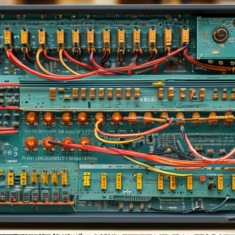
Understanding Hybrid Inverter PCB Functions and System Requirements
How to Choose the Right Hybrid Inverter PCB?
Understanding Hybrid Inverter PCB Functions and System Requirements
A hybrid inverter PCB controls energy flow between solar panels, batteries, household loads, and the electrical grid. It manages power conversion, charging, monitoring, and protective shutdowns. Its design must match the inverter’s voltage, current, and power ratings. Small errors matter. A PCB rated for 48-volt batteries may not suit a higher-voltage storage system. Engineers should verify peak current, switching frequency, and expected duty cycles before selecting components.
The PCB also requires accurate sensing circuits for voltage, current, temperature, and insulation conditions. These signals help the controller respond when a battery overheats or a grid voltage changes suddenly. Power semiconductors need suitable gate drivers, heat paths, and spacing. Poor thermal design can create hot spots near switching devices. Adequate creepage distance, reinforced isolation, grounding, and electromagnetic compatibility controls support safer operation. Communication interfaces should match the battery management system and monitoring hardware.
In practical testing, I examine the PCB under normal load, startup surge, and battery fault conditions. I also inspect connectors, fuse placement, airflow, and service access. A compact layout is useful, but it may limit cooling and repairs. That trade-off deserves attention. I have seen promising prototypes fail because temperature sensors were placed too far from the hottest components. Reliable selection depends on measured performance, documented test results, and realistic installation conditions, not only catalogue specifications.
How to Choose the Right Hybrid Inverter PCB? - Understanding Hybrid Inverter PCB Functions and System Requirements
A hybrid inverter PCB must handle different current levels across the PV, battery, and AC paths. The chart shows the ideal full-power current calculated with I = P / V for a representative 5 kW system: 400 V PV input, 48 V battery input, and 230 V AC output. Actual PCB selection should also include design margins for temperature rise, switching ripple, startup surges, protection devices, and connector ratings.
Matching PCB Voltage, Power, and Battery Compatibility
How to Choose the Right Hybrid Inverter PCB?
Choosing the right hybrid inverter PCB starts with voltage matching. Check the battery’s nominal voltage, full-charge voltage, and inverter DC operating range. A 48 V battery may reach about 58.4 V when fully charged, depending on its chemistry and settings. The PCB must tolerate that peak, not just the label. Measure actual values with a calibrated meter during startup and heavy loads. I have seen capable boards reset after a brief voltage rise. Small details matter.
Tips: Estimate continuous and surge power separately. A 5 kW inverter can demand more than 100 A from a 48 V battery during peak operation. Select PCB traces, connectors, switches, and protection devices for that current, with sensible thermal margin. Inspect copper thickness and cooling paths. A warm connector is a warning, not a design feature.
Battery compatibility involves more than voltage. Confirm the PCB supports the battery chemistry, charging limits, temperature sensors, and BMS communication method. Lithium systems may require accurate cutoff control and data exchange. Lead-based batteries often need different charging stages. I once focused too heavily on rated power and overlooked the communication interface. The prototype worked, but protection functions were unavailable. Recheck the battery manual, connector pinout, and firmware requirements before assembly. Imperfect assumptions become expensive faults.
Evaluating Circuit Design, Protection Features, and Thermal Control
Choosing a hybrid inverter PCB starts with its circuit architecture, not its advertised power rating. IRENA’s Renewable Capacity Statistics 2024 reported about 1,419 GW of global solar capacity by the end of 2023. That scale increases pressure on compact, serviceable designs. Check whether the PCB separates high-voltage and control circuits clearly. Short copper paths reduce losses, while adequate creepage and clearance support safer operation. Use current sensors near switching devices, not far away on a crowded board. Small layout choices matter.
Protection features should match real fault conditions. Look for input overvoltage protection, reverse-polarity protection, short-circuit detection, surge protection, and controlled battery isolation. A fuse alone is not enough. The circuit should identify abnormal current quickly and shut down without damaging nearby components. IEC 62109 requirements are useful references for power-conversion safety. Still, compliance claims need test records. Marketing language is not evidence.
Thermal control often decides PCB life. The IEA PVPS Trends 2024 report recorded roughly 447 GW of new photovoltaic capacity in 2023, meaning more systems operate in hot, dusty, and variable environments. Inspect copper thickness, thermal vias, heatsink contact, and airflow around MOSFETs and capacitors. A temperature sensor beside the hottest switching node is more useful than one near the board edge. Keep thermal paths short. Do not trust simulations alone. Real chamber testing can reveal connector heating, uneven airflow, or a fan that fails too early. I would also question designs that look perfect on paper but lack field-service data.
Checking Component Quality, Certifications, and Manufacturing Standards
Choosing the right hybrid inverter PCB starts with component evidence, not appearance. The IEA PVPS Trends 2024 report recorded about 456 GW of new solar capacity in 2023. That rapid expansion increases pressure on inverter reliability and service life.
Check MOSFET or IGBT voltage ratings, capacitor ripple-current data, and operating-temperature limits. Ask for manufacturer lot codes and traceability records. Look for capacitors rated at 105°C or higher, especially near heat sinks. Thermal cycling results matter. So does vibration testing. A PCB with neat soldering can still fail under repeated load changes.
Certifications should match the installation market. IEC 62109-1 and IEC 62109-2 address inverter safety, while IEC 62477-1 covers power electronic systems. UL 1741 may apply in North America. For production quality, IPC-A-610 and J-STD-001 provide useful assembly benchmarks. ISO 9001 is helpful, but it does not prove every board is reliable. The ISO Survey 2023 recorded more than 1.2 million ISO 9001 certificates worldwide. That scale shows its value, but also its limitation.
Request inspection records, X-ray images for hidden solder joints, and functional test results. Confirm whether the factory uses automated optical inspection and controlled reflow profiles. Ask how failed boards are quarantined. Be cautious with incomplete answers. No inspection is perfect. I would also review field-return data, even when the sample is small. A certificate can look impressive while weak thermal design remains unseen.

